Demo
Add products to your Toolbox to save it for requesting a quote while you keep browsing for other products to complete your list.
Toolbox


 + SCC120")
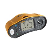
FLUKE 125B-EU-S Industrial ScopeMeter (40 MHz) + SCC120
# 125B-EU-S
- Dual-input digital oscilloscope and multi-meter
- 40 MHz oscilloscope bandwidth
- Two 5000-count True RMS digital multi-meters
Fluke 125B/S Offers
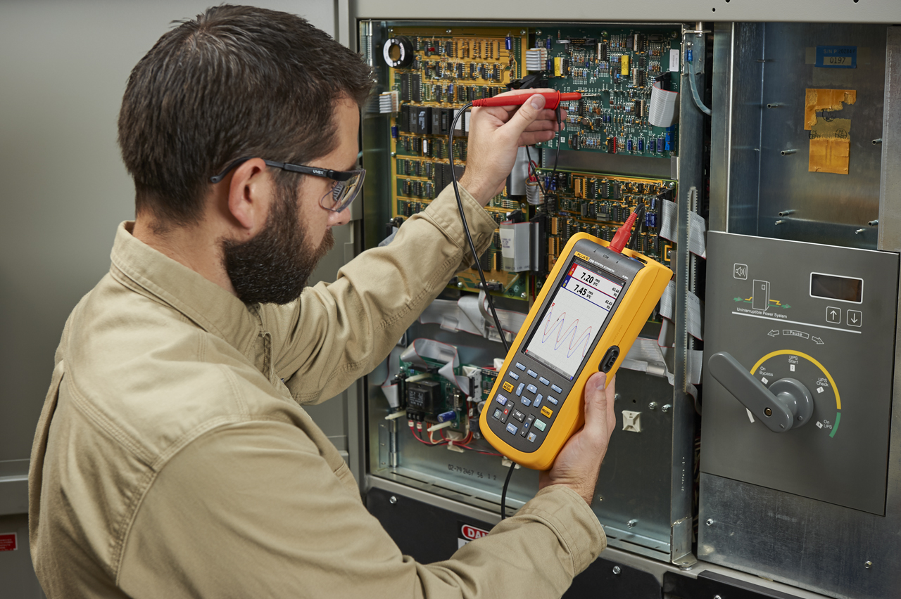
It features innovative functions that help technicians troubleshoot faster and obtain the answers they need to keep their systems going. This handheld oscilloscope also allows users to automatically view related numerical measurements due to it’s Fluke IntellaSet™ technology. Additionally, it comes with Recorder Event Detect capabilities, which capture intermittent events and logs them for simple viewing and analysis.
Features
- Dual-input digital oscilloscope and multimeter
- 40 MHz oscilloscope bandwidth
- Two 5000-count True RMS digital multimeters
- Connect-and-View™ trigger simplicity for hands-off operation
- IntellaSet™ technology automatically and intelligently adjusts numerical readout based on the measured signal
- Dual-input waveform and meter reading recorder for trending data over extended periods
- Recorder Event Detect captures elusive intermittent signals on repetitive waveforms up to 4 kHz
- Shielded test leads for oscilloscope, resistance and continuity measurements
- Resistance, continuity, diode and capacitance meter measurements
- Power measurements (W, VA, VAR, PF, DPF, Hz)
- Voltage, current and power harmonics
- Check Industrial networks with BusHealth physical layer tests against defined reference levels
- Save or recall data and instrument setups
- Store instrument setups defined by a test sequence for routine maintenance or most often used test procedures
- External optically isolated USB interface to transfer, archive and analyze scope or meter data
- Optional WiFi adapter connected to internal USB port to wirelessly transfer information to the PC, laptop or Fluke Connect® mobile app
- FlukeView® ScopeMeter® Software for Windows®
- Rugged design to withstand 3g Vibration, 30g shock, and rated IP51 according to EN/IEC60529
- Highest safety rating in the industry: safety rated for CAT IV 600 V
Connect-and-View™ triggering for an instant, stable display
Oscilloscope users know how difficult triggering can be. Using the wrong settings can lead to unstable waveform captures, and sometimes the wrong measurement data. This instrument’s unique Connect-andView™ triggering technology recognizes signal patterns, and automatically sets up the correct triggering to provide a stable, reliable and repeatable display. Connect-and-View™ triggering is designed to work with virtually any signal, including motor drives and control signals – without adjusting parameters, or even touching a button. Signal changes are instantly recognized and settings are automatically adjusted, providing a stable display even when measuring multiple test points in quick succession.
IntellaSet™/AutoReading
The Auto Readings function with Fluke IntellaSet™ technology uses proprietary algorithms to intelligently analyze the measured waveform and automatically displays the most appropriate numerical measurements on screen, so you can get the data you need easier than ever before. As an example, when the measured waveform is a line voltage signal, the Vrms and Hz readings are automatically displayed, whereas if the measured waveform is a square wave, the peak-peak and Hz readings are automatically displayed. Using IntellaSet™ technology in conjunction with Connect-and-View™ automatic triggering you can be sure you’re seeing not only the correct waveform, but the appropriate numerical reading as well. All without touching a button.
| Oscilloscope Mode – Vertical | |
| Frequency Response – DC Coupled | Without probes and test leads (with BB120): DC to 40 MHz (-3 dB) With STL120-IV 1:1 shielded test leads: DC to 12.5 MHz (-3 dB)/DC to 20 MHz (-6 dB) With VP41 10:1 Probe: DC to 40 MHz (-3 dB) |
| Frequency Response – AC Coupled (LF Roll Off) | Without probes and test leads: <10 Hz (-3 dB) With STL120-IV 1:1 shielded test leads: <10 Hz (-3 dB) With VP41 10:1 Probe: <10 Hz (-3 dB) |
| Rise Time, Excluding Probes, Test Leads | <8.75 ns |
| Input Impedance | Without probes and test leads: 1 MΩ//20 pF With BB120: 1 MΩ//24 pF With STL120-IV 1:1 shielded test leads: 1 MΩ//230 pF With VP41 10:1 Probe: 5 MΩ//15.5 pF |
| Sensitivity | 5 mV to 200 V/div |
| Analog Bandwidth Limiter | 10 kHz |
| Display Modes | A, -A, B, -B |
| Maximum Input Voltage A and B | Direct, with test leads, or with VP41 Probe: 600 Vrms Cat IV, 750 Vrms maximum voltage With BB120: 600 Vrms |
| Maximum Floating Voltage, From any Terminal to Ground | 600 Vrms Cat IV, 750 Vrms up to 400 Hz |
| Oscilloscope Mode – Horizontal | |
| Scope Modes | Normal, Single, Roll |
| Ranges (Normal) | Equivalent sampling: 10 to 500 ns/div Real time sampling: 1 µs to 5 s/div Single (real time): 1 µs to 5 s/div Roll (real time): 1s to 60 s/div |
| Sampling Rate (For Both Channels Simultaneously) | Equivalent sampling (repetitive signals): Up to 4 GS/s Real time sampling 1 µs to 60 s/div: 40 MS/s |
| Trigger | |
| Screen Update | Free run, on trigger |
| Source | A, B |
| Sensitivity A and B | At DC to 5 MHz: 0.5 divisions or 5 mV At 40 MHz: 1.5 divisions At 60 MHz: 4 divisions |
| Slope | Positive, negative |
| Advanced Scope Functions | |
| Display Modes – Normal | Captures up to 25 ns glitches and displays analog-like persistence waveform |
| Display Modes – Smooth | Suppresses noise from a waveform |
| Display Modes – Glitch Off | Does not capture glitches between samples |
| Display Modes – Envelope | Records and displays the minimum and maximum of waveforms over time |
| Auto Set (Connect-and-View™) | Continuous fully automatic adjustments of amplitude, time base, trigger levels, trigger gap, and hold-off. Manual override by user adjustment of amplitude, time base, or trigger level. |
| DC Voltage (VDC) | |
| Ranges | 500 mV, 5 V, 50 V, 500 V, 750 V |
| Accuracy | ±(0.5% +5 counts) |
| Common Mode Rejection (CMRR) | >100 dB at DC >60 dB at 50, 60, or 400 Hz |
| Full Scale Reading | 5000 counts |
| True RMS Voltages (V AC and V AC/DC) | |
| Ranges | 500 mV, 5 V, 50 V, 500 V, 750 V |
| Accuracy for 5 to 100% of Range (DC Coupled) | DC to 60 Hz (V AC/DC): ±(1% +10 counts) 1 to 60 Hz (V AC): ±(1% +10 counts) |
| Accuracy for 5 to 100% of Range (AC or DC Coupled) | 60 Hz to 20 kHz: ±(2.5% +15 counts) |
| DC Rejection (Only VAC) | >50 dB |
| Common Mode Rejection (CMRR) | >100 dB at DC >60 dB at 50, 60, or 400 Hz |
| Full Scale Reading | 5000 counts, reading is independent of any signal crest factor |
| Peak | |
| Modes | Max peak, Min peak, or pk-to-pk |
| Ranges | 500 mV, 5 V, 50 V, 500 V, 2200 V |
| Accuracy | Accuracy Max peak or Min peak: 5% of full scale Accuracy Peak-to-Peak: 10% of full scale |
| Full Scale Reading | 500 counts |
| Frequency (Hz) | |
| Ranges | 1 Hz, 10 Hz, 100 Hz, 1 kHz, 10 kHz, 100 kHz, 1 MHz, 10 MHz, and 70 MHz |
| Frequency Range | 15 Hz (1 Hz) to 50 MHz in continuous autoset |
| Accuracy at 1 Hz to 1 MHz | ±(0.5% +2 counts) |
| Full Scale Reading | 10,000 counts |
| RPM | |
| Maximum Reading | 50.00 kRPM |
| Accuracy | ±(0.5% +2 counts) |
| Duty Cycle (PULSE) | |
| Range | 2 to 98% |
| Frequency Range | 15 Hz (1 Hz) to 30 MHz in continuous autoset |
| Pulse Width (PULSE) | |
| Frequency Range | 15 Hz (1 Hz) to 30 MHz in continuous autoset |
| Full Scale Reading | 1000 counts |
| Amperes (AMP) | |
| With Current Clamp | Ranges: Same as V dc, V ac, V ac+dc, or PEAK Scale factors: 0.1 mV/A, 1 mV/A, 10 mV/A, 100 mV/A, 400 mV/A, 1 V/A, 10 mV/mA Accuracy: Same as V dc, V ac, V ac+dc, or PEAK (add current clamp uncertainty) |
| Temperature (TEMP) with Optional Temperature Probe | |
| Range | 200°F/div (200°C/div) |
| Scale Factor | 1 mV/°F and 1 mV/°C |
| Accuracy | As V dc (add temp. probe uncertainty) |
| Decibel (dB) | |
| 0 dBV | 1 V |
| 0 dBm (600 Ω/50 Ω) | 1 mW referenced to 600 Ω or 50 Ω |
| dB on | V DC, V AC, or V AC+DC |
| Full Scale Reading | 1000 counts |
| Crest Factor (CREST) | |
| Range | 1 to 10 |
| Full Scale Reading | 90 Counts |
| Phase | |
| Modes | A to B, B to A |
| Range | 0 to 359° |
| Resolution | 1° |
| Power | |
| Configurations | 1 phase/3 phase 3 conductor balanced loads (3 phase: fundamental component only, AUTOSET mode only) |
| Power Factor (PF) | Ratio between watts and VA range – 0.00 to 1.00 |
| Watt | RMS reading of multiplying corresponding samples of input A (volts) and input B (amperes) Full scale reading: 999 counts |
| VA | Vrms x Arms Full scale reading: 999 counts |
| VA Reactive (Var) | √((VA)2-W2) Full scale reading: 999 counts |
| Vpwm | |
| Purpose | To measure on pulse width modulated signals, like motor drive inverter outputs |
| Principle | Readings show the effective voltage based on the average value of samples over a whole number of periods of the fundamental frequency |
| Accuracy | As Vrms for sinewave signals |
| Input A to Common – (Ω) | |
| Ranges | 500 Ω , 5 kΩ, 50 kΩ, 500 kΩ, 5 MΩ, 30 MΩ |
| Accuracy | ±(0.6% + 5 counts) 50 Ω ±(2% + 20 counts) |
| Full Scale Reading | 50 Ω to 5 MΩ at 5000 counts, 30 MΩ at 3000 counts |
| Measurement Current | 0.5 mA to 50 nA, decreases with increasing ranges |
| Open Circuit Voltage | <4 V |
| Continuity (Cont) | |
| Beep | <(30 Ω ±5 Ω) in 50 Ω range |
| Measurement Current | 0.5 mA |
| Detection of Shorts of | ≥1 ms |
| Diode | |
| Measurement Voltage | At 0.5 mA: >2.8 V At open circuit: <4 V |
| Measurement Current | 0.5 mA |
| Polarity | + on input A, – on COM |
| Capacitance (CAP) | |
| Ranges | 50 nF, 500 nF, 5 µF, 50 µF, 500 µF |
| Full Scale Reading | 5000 counts |
| Measurement Current | 500 nA to 0.5 mA, increases with increasing ranges |
| Advanced Meter Functions | |
| Zero Set | Set actual value to reference |
| AutoHold (on A) | Captures and freezes a stable measurement result. Beeps when stable. AutoHold works on the main meter reading, with thresholds of 1 Vpp for AC signals and 100 mV for DC signals. |
| Fixed Decimal Point | Activated by using attenuation keys |
| Cursor Readout | |
| Sources | A, B |
| Single Vertical Line | Average, min and max readout Average, min, max and time from start of readout (in ROLL mode; instrument in HOLD) Min, max and time from start of readout (in RECORDER mode; instrument in HOLD) Harmonics values in POWER QUALITY mode. |
| Dual Vertical Lines | Peak-peak, time distance and reciprocal time distance readout Average, min, max and time distance readout (in ROLL mode; instrument in HOLD) |
| Dual Horizontal Lines | High, low and peak-peak readout |
| Rise or Fall Time | Transition time, 0%-level and 100%-level readout (manual or auto leveling; auto leveling only possible in single channel mode) |
| Accuracy | As oscilloscope accuracy |
| Meter Readings | |
| Measurement Speed | Maximum 2 measurement/s |
| Record Size (Min, Max, Average) | 2 M readings for 1 channel |
| Recorded Time Span | 2 weeks |
| Maximum Number of Events | 1024 |
| Waveform Record | |
| Maximum Sample Rate | 400 K sample/s |
| Size Internal Memory | 400 M samples Recorded Time |
| Span Internal Memory | 15 minutes at 500 µs/div 11 hours at 20 ms/div |
| Record Size SD Card | 1.5 G samples |
| Recorded Time Span SD Card | 11 hours at 500 µs/div 14 days at 20 ms/div |
| Maximum number of Events | 64 |
| Power Quality | |
| Readings | Watt, VA, var, PF, DPF, Hz |
| Watt, VA, Var Ranges (Auto) | 250 W to 250 MW, 625 MW, 1.56 GW |
| When Selected: Total (% r) | ±(2% + 6 counts) |
| When Selected: Fundamental (% f) | ±(4% + 4 counts) |
| DPF | 0.00 to 1.00 |
| PF | 0.00 to 1.00, ±0.04 |
| Frequency Range | 10.0 Hz to 15.0 kHz 40.0 to 70.0 Hz |
| Number of Harmonics | DC to 51 |
| Readings/Cursor Readings (Fundamental 40 to 70 Hz) | Vrms /Arms/Watt Each harmonic from fundamental maybe selected for individual readings |
| BusHealth Tester | |
| AS-i | NEN-EN50295 |
| CAN | ISO-11898 |
| Interbus S | Subtype: RS-422 Protocol: EIA-422 |
| Modbus | Subtype: RS-232, Protocol: RS-232/EIA-232 Subtype: RS-485, Protocol: RS-485/EIA-485 |
| Foundation Fieldbus | Subtype: H1 Protocol: 61158 type 1, 31.25 kBit |
| Profibus | Subtype: DP, Protocol: EIA-485 Subtype: PA, Protocol: 61158 type 1 |
| Miscellaneous | |
| Display | Type: 5.7″ color active matrix TFT Resolution: 640 x 480 pixels |
| Waveform Display | Vertical: 10 div of 40 pixels Horizontal: 12 div of 40 pixels |
| Power | External: Via Power Adapter BC430 Input voltage: 10 to 21 V DC Power consumption: 5 W typical Input connector: 5 mm jack Internal: Via Battery Pack BP290 Battery power: Rechargeable Li-Ion 10.8 V Operating time: 7 hours with 50% backlight brightness Charging time: 4 hours with test tool off, 7 hours with test tool on Allowable ambient temperature: 32 to 104°F (0 to 40°C) during charging |
| Memory | Internal memory can store 20 data sets (screen waveform and setup) Micro SD card slot with optional SD card (max size of 32 GB) |
| Interface | |
| Optically Isolated | Transfer screen copies (bitmaps), settings and data |
| USB to PC/Laptop | OC4USB optically isolated USB adapter/cable, (optional), using FlukeView® software for Windows®. |
| Optional WiFi Adapter | Fast transfer of screen copies (bitmaps), settings and data to PC/laptop, tablet, smartphone, etc. A USB port is provided for attaching the WiFi dongle. Do not use the USB port with a cable for safety reasons. |
| General Specifications | |
| Environmental | MIL-PRF-28800F, Class 2 |
| Temperature | Battery Operation: 32 to 104°F (0 to 40°C) Power Adapter Operation: 32 to 122°F (0 to 50°C) Storage: -4 to 140°F (-20 to 60°C) |
| Humidity (Operating) | Non-condensing at 32 to 50°F (0 to 10°C) 95% at 50 to 86°F (10 to 30°C) 75% at 86 to 104°F (30 to 40°C) 45% at 104 to 122°F (40 to 50°C) |
| Storage | Non-condensing at -4 to 140°F (-20 to 60°C) |
| Altitude | Operating at 10,000′ (3 km): CAT III 600 V Operating at 6600′ (2 km): CAT IV 600 V Storage: 40,000′ (12 km) |
| Wireless Radio with Adapter | Frequency Range: 2412 to 2462 MHz Output power: <100 mW |
| Maximum input voltage input A and B | Direct on input or with leads: 600 Vrms CAT IV for derating With Banana-to-BNC Adapter BB120: 600 Vrms for derating Maximum floating voltage from any terminal to ground: 600 Vrms Cat IV, 750 Vrms up to 400 Hz |
| Dimensions | 10.2 x 5.2 x 2.15″ (259 x 132 x 55 mm) |
| Weight | 3.2 lbs (1.4 kg) |
| Safety | General: IEC 61010-1: Pollution Degree 2 Measurement: IEC 61010-2-033: CAT IV 600 V/CAT III 750 V |
| Enclosure Protection | IP51, ref: EN/IEC60529 |
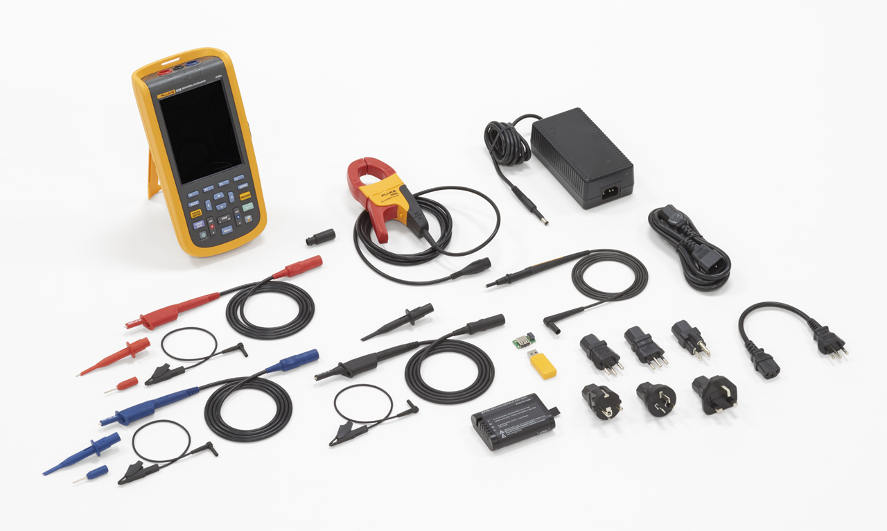
- Fluke 125B Hand-Held Oscilloscope
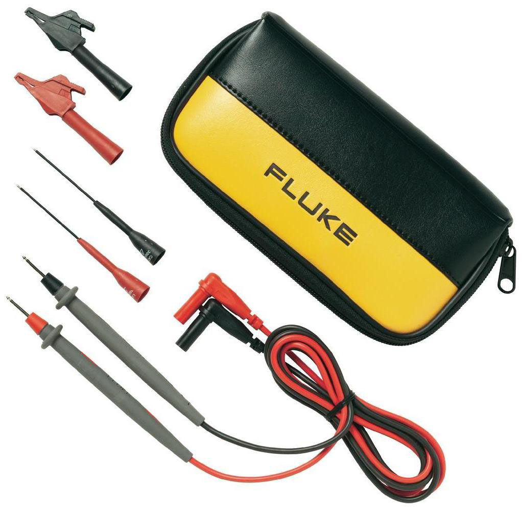
- Shielded Test Leads with Black Ground Leads
- Test Lead Black (for Grounding)
- Hook Clips (red, blue)
- Banana-to-BNC Adapters (black, x1)
- 10:1 Voltage Probe
- i400s AC Current Clamp
- USB Angled Adapter
- WiFi USB Adapter*
- Switch Mode Power Supply, Adapter/Battery Charger
- Rechargeable Li-ion Battery Pack
- Soft Carrying Case
- Magnetic Hanger
- FlukeView® ScopeMeter® Software for Windows®
- Screen Protector
Related Products


Explore More in Electrical Testers


Explore More in Testing Equipment


Provide us your contact detailsone of our product experts will contact you to discuss your needs or schedule a demonstration at a time that suits
Product selected: Model #
*Demonstrations can only be scheduled within the UAE