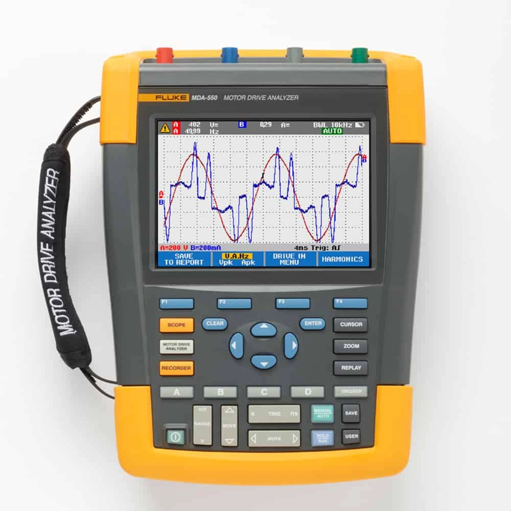
• Store Locator
  • Schedule a
    Demo
  • Add products to your Toolbox to save it for requesting a quote while you keep browsing for other products to complete your list.

    My
    Toolbox
  • Create a Requisition

    FLUKE MDA-550 Motor Drive Analyzer 550, 4-channel color, PRO

    # MDA-550

    • Guided testing with graphical step-by-step voltage and current connection diagrams makes setup and connection to variable frequency drives easier than ever
    • Preset measurement profiles collect data based on the chosen test procedure and reduce the need for complex configuration
    • Built-in report writing capabilities make it easy to produce professional as-found and as-left motor-drive troubleshooting reports

    Ready to see it in action? Please provide us with your contact information, and one of our technical experts will contact you to schedule your product demonstration.

    Simplify complex motor-drive troubleshooting with guided test setups and automated drive measurements that provide reliable, repeatable test results.


    • Measure key motor-drive parameters including voltage, current, DC Bus voltage level and AC ripple, voltage and current unbalance and harmonics (MDA-550), voltage modulation, and motor shaft voltage discharges (MDA-550).
    • Perform extended harmonics measurements to identify the effects of low and high order harmonics on your electrical power system.
    • Conduct guided measurements for motor-drive input, DC bus, drive output, motor input and shaft measurements (MDA-550) with graphical step-by-step voltage and current connection diagrams.
    • Use simplified measurement setup with preset measurement profiles to automatically trigger data collection based on the chosen test procedure.
    • Create reports quickly and easily that are perfect for documenting troubleshooting and collaborative work with others.
    • Measure additional electrical parameters with full 500 MHz oscilloscope, meter and recording capability for complete range of electrical and electronic measurement on industrial systems.


    The Fluke MDA-510 and MDA-550 Motor Drive Analyzers use guided test measurements to make analysis easier than ever.


    Drive input


    Measure input voltage and current to quickly see whether values are within acceptable limits by comparing the variable frequency drive’s (VFD), also known as a variable speed drive (VSD) or adjustable speed drive (ASD), nominal rated voltage to the actual supplied voltage. Then, check the input current to determine if the current is within the maximum rating and the conductors are suitably sized. You can also check whether the harmonic distortion is within an acceptable level by visually inspecting the waveform shape or by viewing the harmonics spectrum screen (MDA-550) with total harmonic distortion and individual harmonics.


    Voltage and current unbalance


    Check the voltage unbalance at the input terminals of the frequency speed drive so you can ensure the phase unbalance is not too high (> 6-8 %), and that the phase rotation is correct. You can also check the current unbalance, as excessive unbalance may indicate a drive rectifier problem.


    Extended harmonic measurements


    Excessive harmonics are not just a threat to your rotating machines but also to other equipment connected to the electrical power system. The MDA-550 provides the ability to discover the harmonics of the motor-drive but can also discover the possible effects of inverter switching electronics. The MDA-550 has three harmonic ranges, 1st to 51st Harmonics, 1 to 9 kHz and 9 kHz to 150 kHz giving the ability to detect any harmonic pollution problems.


    DC bus


    In a motor-drive the conversion of AC to DC inside the drive is critical, having the correct voltage and adequate smoothing with low ripple is required for the best drive performance. High ripple voltage may be an indicator of failed capacitors or incorrect sizing of the connected motor. The record function of the MDA-500 Series can be used to check DC bus performance dynamically in the operating mode while a load is applied.


    Drive output


    Check the output of the inverter drive focusing both on voltage to frequency ratio (V/F), and voltage modulation. When high V/F ratio measurements are experienced, the motor may overheat. With low V/F ratios, the connected motor may not be able to provide the required torque at the load to sufficiently run the intended process.


    Voltage modulation


    Measurements of the Pulse Width Modulated signal are used to check for high voltage peaks which can damage motor winding insulation. The rise time or steepness of impulses is indicated by the dV/dt reading (rate of voltage change over time), this should be compared to the motor’s specified insulation. The measurements can also be used to measure switching frequency to identify whether there is a potential issue with electronic switching, or with grounding, where the signal floats up and down.


    Motor input


    Ensuring that voltage is being supplied at the motor input terminals is key, and the selection of cabling from drive to the motor is critical. Incorrect cabling selection can result in both drive and motor damage due to excessive reflected voltage peaks. Checking that the current present at the terminals is within the motor rating is important as over current condition could cause the motor to run hot, decreasing the life of the stator insulation which can result in the early failure of the motor.


    Motor shaft voltage


    Voltage pulses from a variable frequency drive can couple from a motor’s stator to its rotor, causing a voltage to appear on the rotor shaft. When this rotor shaft voltage exceeds the insulating capacity of the bearing grease, flashover currents (sparking) can occur, causing pitting and fluting of the motor bearing race, damage that can cause a motor to fail prematurely. The MDA-550 Series analyzers are supplied with carbon fiber brush probe tips that can easily detect the presence of destructive flashover currents, while the impulse amplitude and count of events will enable you to take action before failure occurs. The addition of this accessory and capability of the MDA-550 allows you to discover potential damage without investing in expensive permanently installed solutions.


    Step-by-step guided measurements ensure you have the data you need, when you need it


    The MDA-500 Series is designed to help you quickly and easily test and troubleshoot typical problems on three-phase and single-phase inverter type motor-drive systems. The on-screen information, and step-by-step setup guidance make it easy to configure the analyzer and get the drive measurements you need to make better maintenance decisions, fast. From power input to the installed motor, the MDA-500 provides the measurement capability for the fastest motor-drive troubleshooting.

    Measurement Function
    DC voltage (V dc)
    Maximum voltage with 10:1 or 100:1 probe1000 V
    Maximum resolution with 10:1 or 100:1 probe1 mV
    Full scale reading999 counts
    Accuracy at 4 s to 10 us/div±(3 % + 6 counts)
    AC voltage (V ac)
    Maximum voltage with 10:1 or 100:1 probe1000 V
    Maximum resolution with 10:1 or 100:1 probe1 mV
    Full scale reading999 counts
    50 Hz±(3 % + 10 counts) – 0.6 %
    60 Hz±(3 % + 10 counts) – 0.4 %
    60 Hz to 20 kHz±(4 % + 15 counts)
    20 kHz to 1 MHz±(6 % + 20 counts)
    1 MHz to 25 MHz±(10 % + 20 counts)
    True-rms voltage (V ac+dc)
    Maximum voltage with 10:1 or 100:1 probe1000 V
    Maximum resolution with 10:1 or 100:1 probe1 mV
    Full scale reading1100 counts
    DC to 60 Hz±(3 % + 10 counts)
    60 Hz to 20 kHz±(4 % + 15 counts)
    20 kHz to 1 MHz±(6 % + 20 counts)
    1 MHz to 25 MHz±(10 % + 20 counts)
    PWM voltage (V pwm)
    PurposeTo measure on pulse width modulated signals, like motor drive inverter outputs
    PrincipleReadings show the effective voltage based on the average value of samples over a whole number of periods of the fundamental frequency
    AccuracyAs Vac+dc for sinewave signals
    Peak voltage (V peak)
    ModesMax peak, min peak, or pk-to-pk
    Maximum voltage with 10:1 or 100:1 probe1000 V
    Maximum resolution with 10:1 or 100:1 probe10 mV
    Accuracy
    Max peak, min peak±0.2 division
    Pk-to-pk±0.4 division
    Full scale reading800 counts


    General Specification
    Current (AMP) with current clamp
    RangesSame as V ac, Vac+dc or V peak
    Scale Factors0.1 mV/A, 1 mV/A, 10 mV/A, 20 mV/A, 50mV/A, 100 mV/A, 200 mV/A, 400 mV/A
    AccuracySame as Vac, Vac+dc or V peak (add current clamp accuracy)
    Frequency (Hz)
    Range1.000 Hz to 500 MHz
    Full scale reading999 counts
    Accuracy±(0.5 % + 2 counts)
    Voltage/Herz ratio (V/Hz)
    PurposeTo show the measured V PWM value (see V PWM) divided by the fundamental frequency on variable ac motor speed drives
    Accuracy% Vrms + % Hz
    Voltage unbalance drive input
    PurposeTo show the highest percentage difference of one of the phase vs average of the 3 true-rms voltages
    AccuracyIndicative percentage based on Vac+dc values
    Voltage unbalance drive output and motor input
    PurposeTo show the highest percentage difference of one of the phase vs average of the 3 PWM voltages
    AccuracyIndicative percentage based on V PWM values
    Current unbalance drive input
    PurposeTo show the highest percentage difference of one of the phase vs average of the 3 AC current values
    AccuracyIndicative percentage based on Aac+dc values
    Current unbalance drive output and motor input
    PurposeTo show the highest percentage difference of one of the phase vs average of the 3 AC current values
    AccuracyIndicative percentage based on A ac values
    Rise and fall time
    ReadingsVoltage difference (dV), time difference (dt), voltage vs time difference (dV/dt), overshoot
    AccuracyAs oscilloscope accuracy
    Harmonics and spectrum
    HarmonicsDC to 51st
    Spectrum ranges1…9 kHz, 9-150 kHz (20 MHz filter on), up to 500 MHz (voltage modulation)
    Shaft voltage
    Events / secondIndicative percentage based on rise and fall time (Impulse discharges) measurements
    Report data capture
    Number of screensTypical 50 screens can be saved in reports (depends on compression ratio)
    Transfer to PCUsing 2 GB USB stick or mini-USB to USB cable and FlukeView™ 2 for ScopeMeter™ test tool
    Probe settings
    Voltage probe1:1, 10:1, 100:1, 1000:1, 20:1, 200:1
    Current clamp0.1 mV/A, 1 mV/A, 10 mV/A, 20 mV/A, 50 mV/A, 100 mV/A, 200 mV/A, 400 mV/A
    Shaft voltage probe1:1, 10:1, 100:1
    Motor drive analyzer, 4 channel, 500 MHz with motor shaft and harmonics
    • 1x BP 291 li-ion battery pack
    • 1x BC190 charger/power adapter
    • 3x VPS 100:1 high voltage probes with alligator clips
    • 1x VPS410-II-R 10:1 500MHz voltage probe
    • 3x i400s ac current clamp
    • 1x C1740 carrying case
    • 1x 2 GB USB drive with manuals and FlukeView™ 2 software
    • 1x SVS-500 shaft voltage set (3x brush, probe holder, two-piece extension rod and magnetic base)

    Provide us your contact detailsone of our product experts will contact you to discuss your needs or schedule a demonstration at a time that suits

    Product selected: Model #


      *Demonstrations can only be scheduled within the UAE

      Sign up to stay in the know-how of our latest products, updates, special offers, and more.

      • Subscription Form